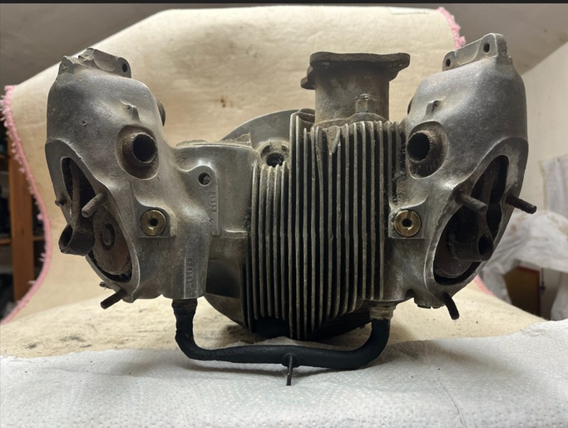
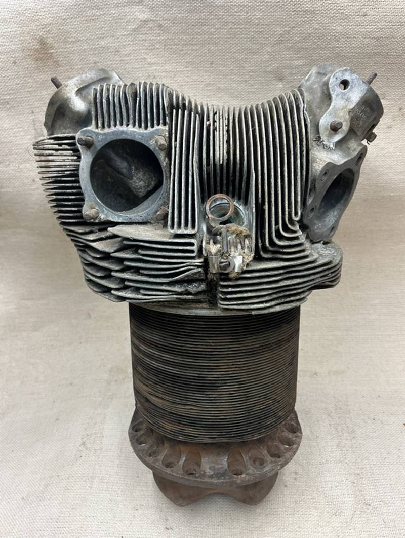
The Pratt & Whitney R-1830 cylinder head is a cast aluminum component that is screwed and shrunk onto a forged steel cylinder barrel. It is a key part of the fourteen-cylinder, two-row, air-cooled radial engine that powered many iconic World War II aircraft.
The cylinder head is designed for efficient air cooling and features specific design elements to ensure durability and optimal performance.
Pratt and Whitney powered the B-24 Liberator, C-47 Skytrain, Douglas DC-3, PBY Catalina, F4F Wildcat, and many others.
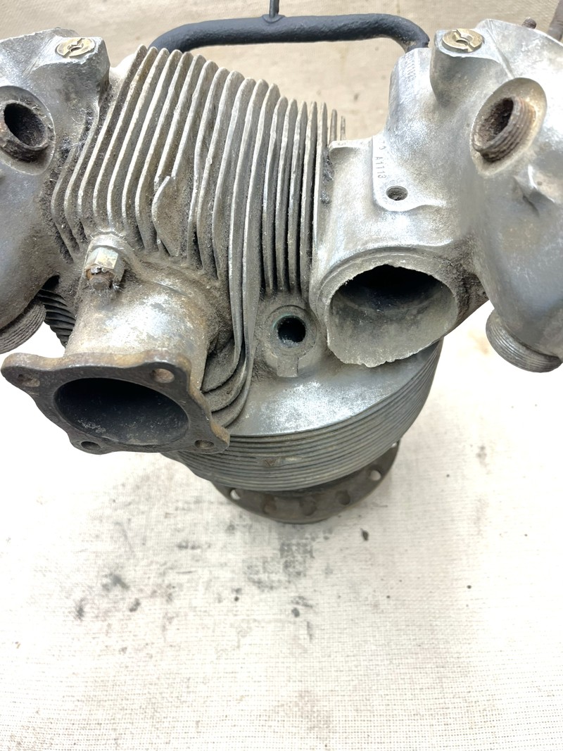
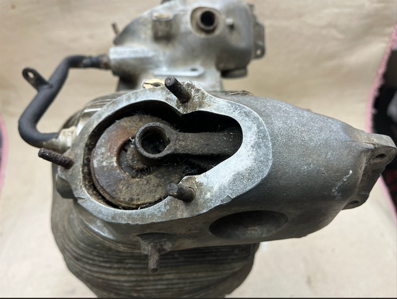
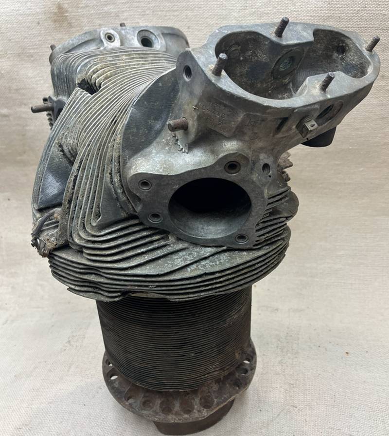
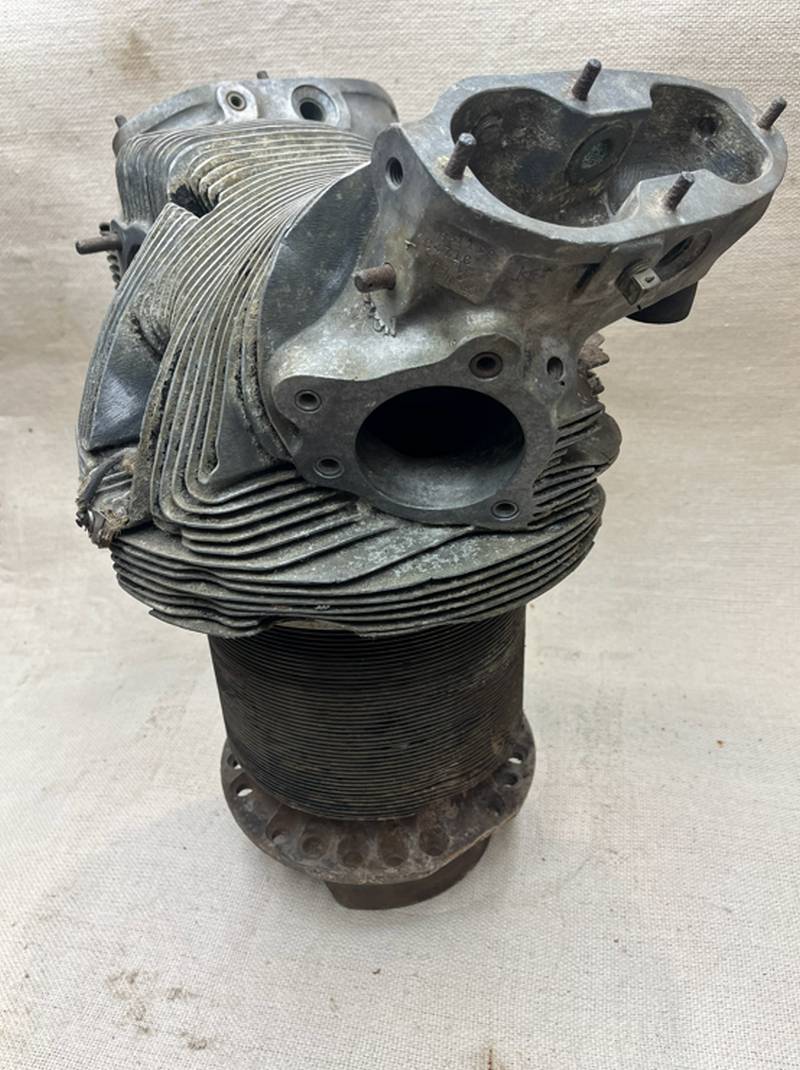
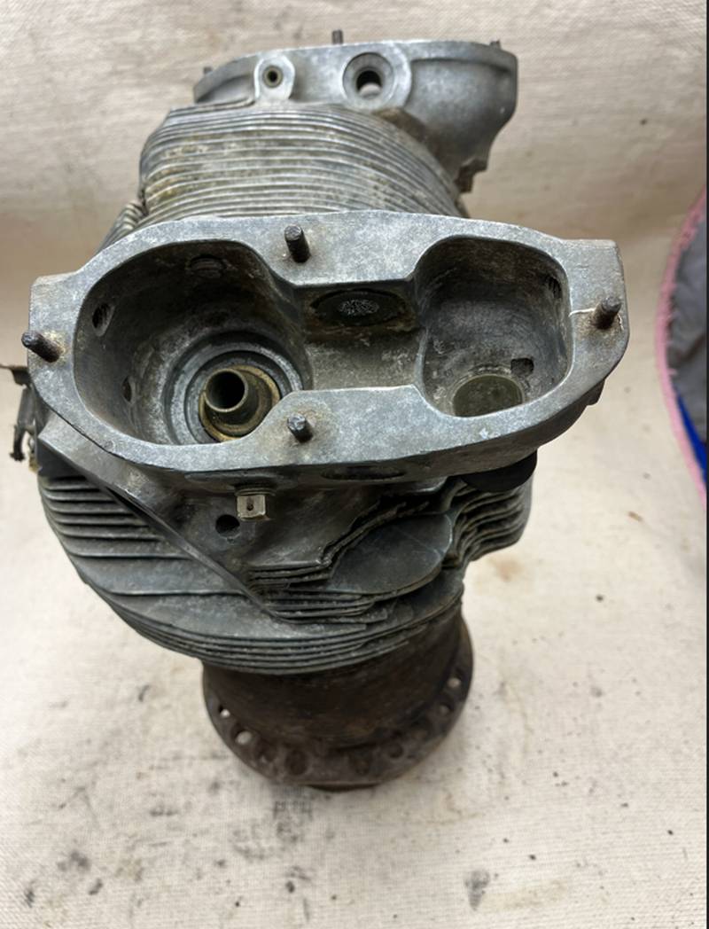
The Cylinder Head is made of cast aluminum with integral valve mechanism housings. Features include a photo showing an intake port on the right and an exhaust port on the left, with a shrunk-in stainless steel liner in the exhaust port. The intake features aluminum bronze valve seats, while the exhaust valve seats are made of steel. The engine also includes fail-safe redundancy for two spark plugs and pressure baffles for enhanced cooling.
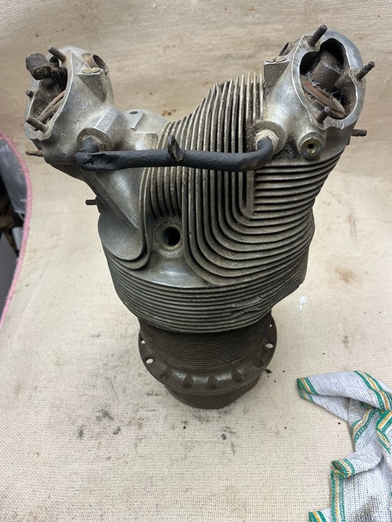
Instead of traditional cast fins, Pratt & Whitney machined the fins directly from the solid metal of the cylinder head forging.
More surface area: This process created a greater surface area for cooling compared to cast fins, which was crucial for the high-performance engines of the era.
The Cylinder Head: Made of cast aluminum with integral valve mechanism housings. Features include intake and exhaust ports with a shrunk-in stainless steel liner in the exhaust port, aluminum bronze intake valve seats and steel exhaust valve seats, two spark plugs, and pressure baffles for cooling.
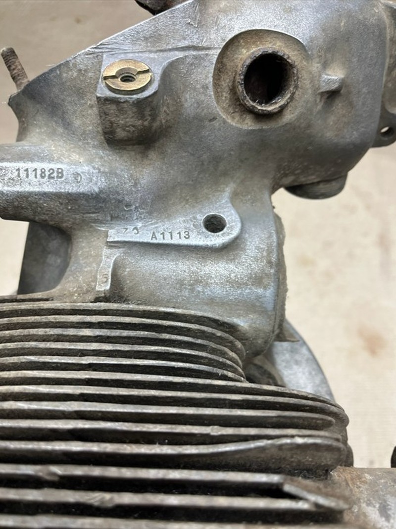
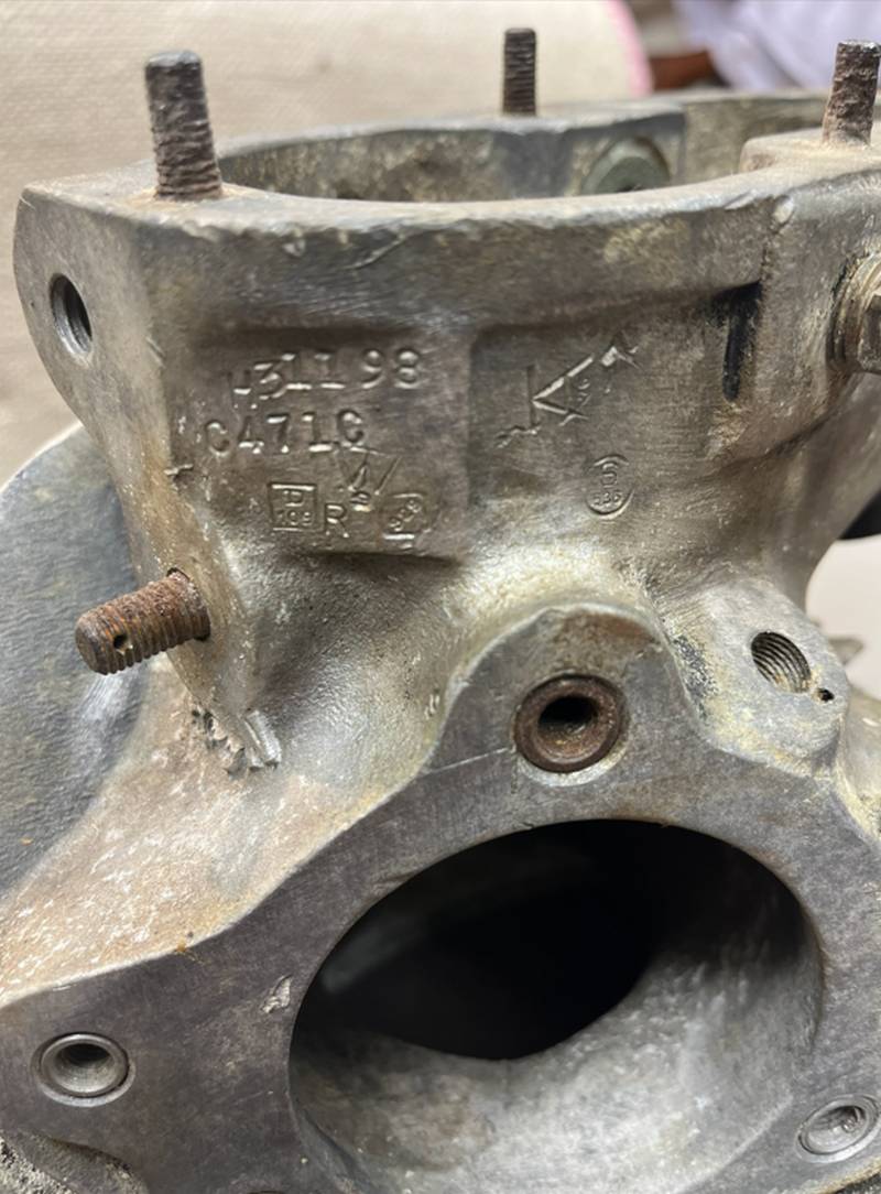
Numbers on the side of the cylinder valve casing are 11182B and A1113.
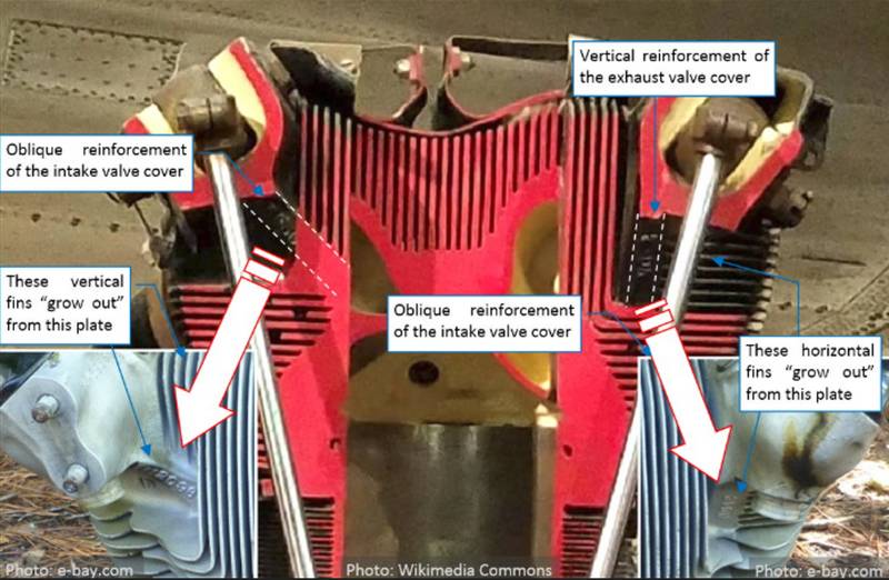
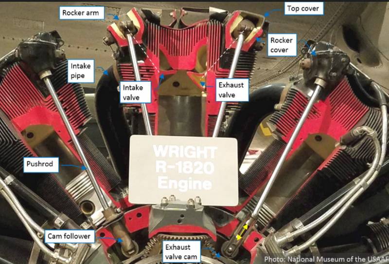
The inlet valve is on the left, and the exhaust valve is on the right. The exhaust side of the cylinder gets hotter than the intake side, so it has more and larger fins to help dissipate heat.

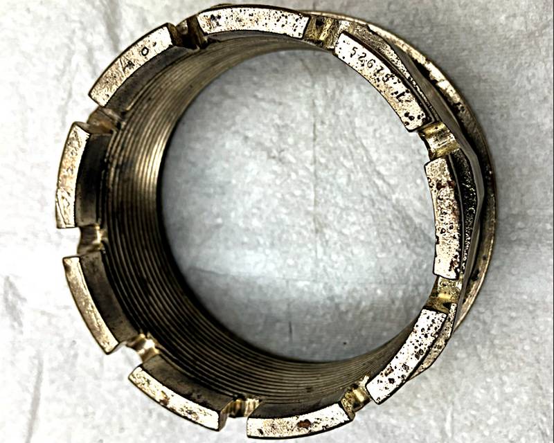
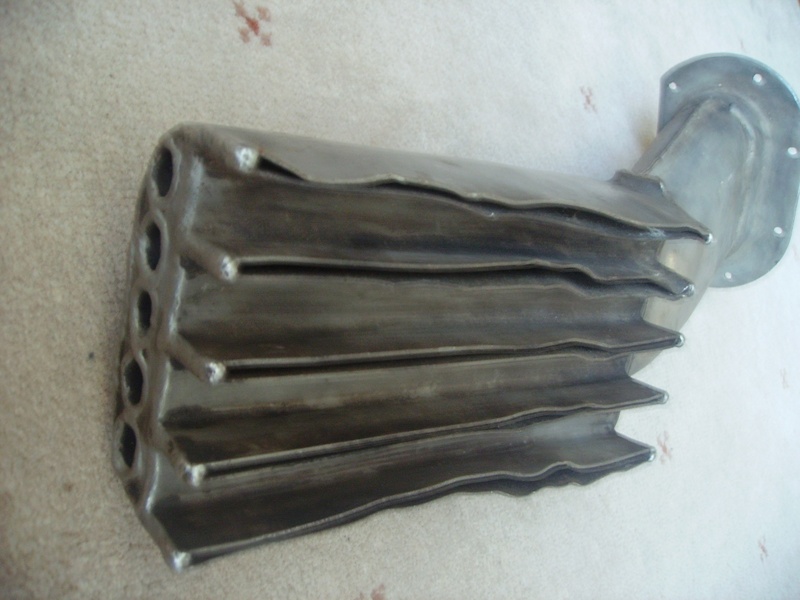
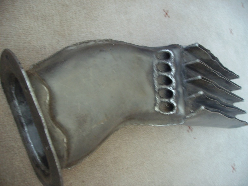
The WW2 Wright Cyclone aircraft engine cylinder head that came from RAF Burtonwood was recovered from a local scrapyard in Warrington.
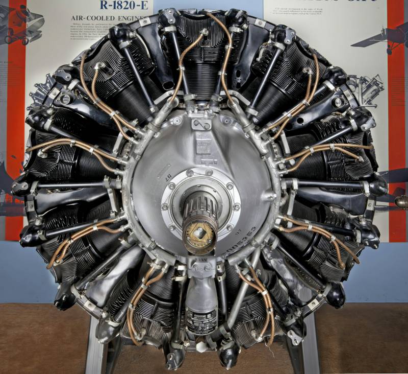
Wright Cyclone cylinder heads (notably on the G Series R-1820) are air-cooled aluminum alloy castings featuring closely spaced "comb-like" fins for high heat dissipation, typically with a 2,800 sq. in cooling area. They use a hemispherical combustion chamber with one sodium-cooled exhaust valve and one intake valve, designed to handle high-power radial engine loads.

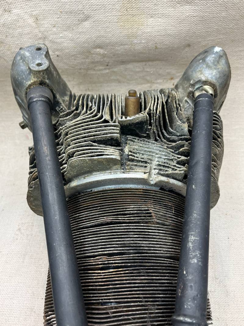
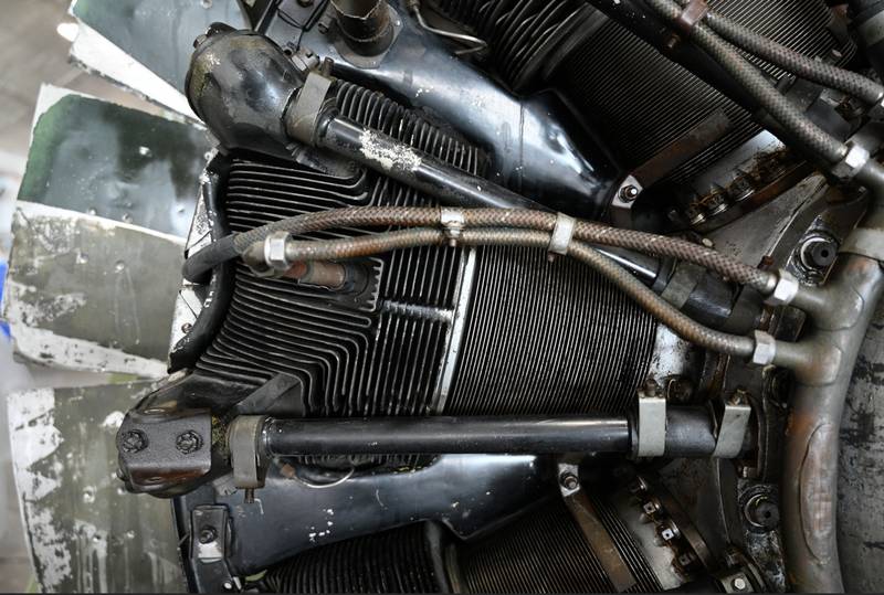
Wright Cyclone side view of the cylinder head, the exhaust port is on the right side, and the intake port is on the left side. The Cooling fins improved heat dissipation. By increasing the surface area, cooling fins facilitate more efficient heat transfer to the surrounding environment. This helps to prevent components from overheating.
This engine was widely used on aircraft from the 1930s through the 1950s. The R-1820 was built under license by Lycoming and Pratt & Whitney Canada, and during World War II by the Studebaker Corporation.
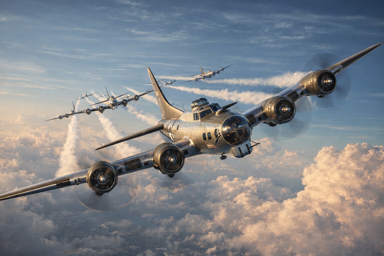
The R-1820 Cyclone 9 engine was the heart of many famous aircraft, including early Douglas airliners (the prototype DC-1, the DC-2, the first civilian versions of the DC-3, and the limited production DC-5), every war time example of the Boeing B-17 Flying Fortress and Douglas SBD Dauntless bombers, the early versions of the Polikarpov I-16 (as the M-25), and the Piasecki H-21 helicopter.
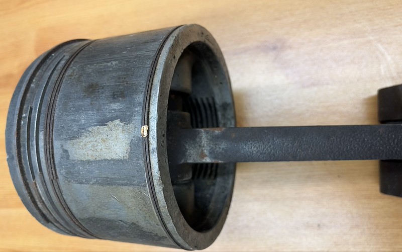
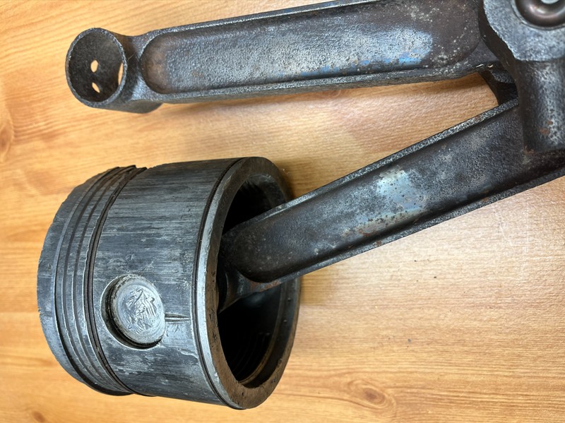
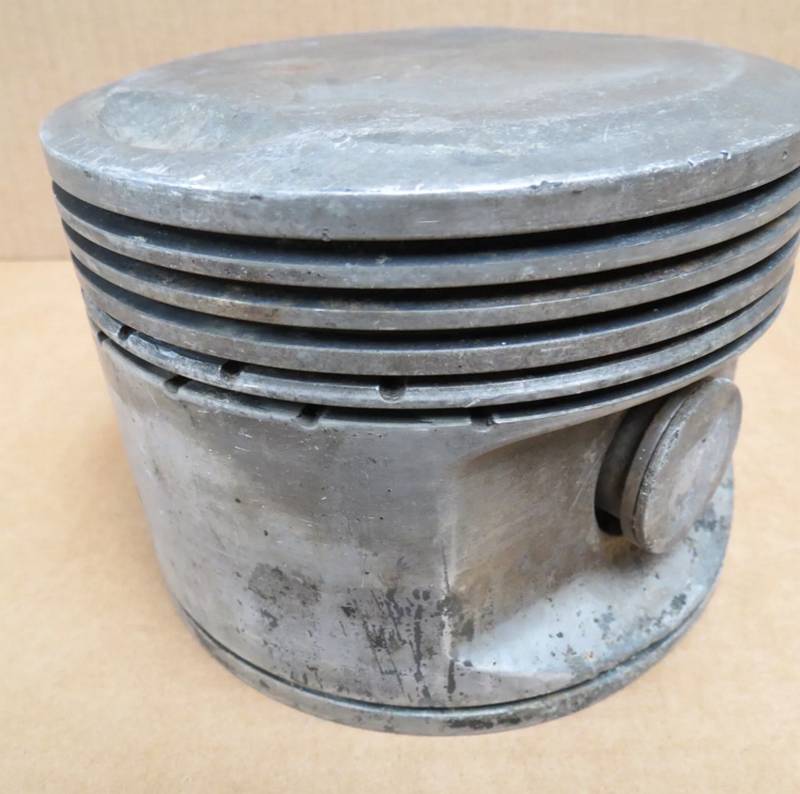
A few general characteristics of the Wright R-1820 Cyclone 9 are that it is a Nine-cylinder single-row supercharged air-cooled radial engine, has a 6.125” Bore Cylinder, and only needed 87 octane rating gasoline. Each cylinder had 2 spark plugs. The piston was found at a Warrington scrap yard.
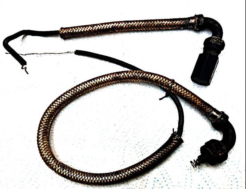
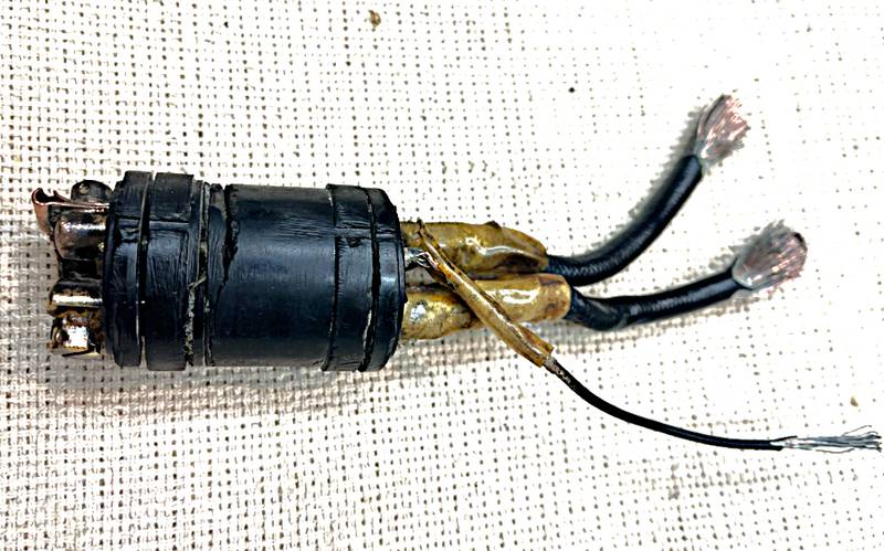
The ignition cables were robust with a metal braided outer layer for durability and shielding against radio interference, and mechanical protection. The cable inside also had a black rubber-like insulation. Also, each cylinder had 2 spark plugs. The cable order number is p/n54408-nos.
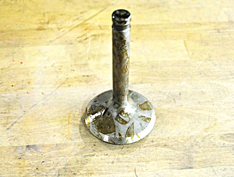
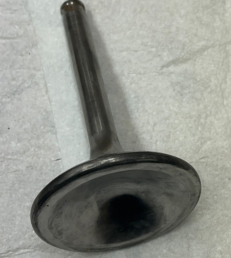
There sodium-cooled exhaust valves were a critical component, with the high-stress, high-temperature environment of the radial engine making effective heat management through sodium cooling essential for reliability. A Mary Ann Site find at Burtonwood.
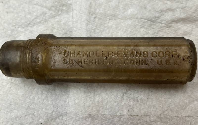
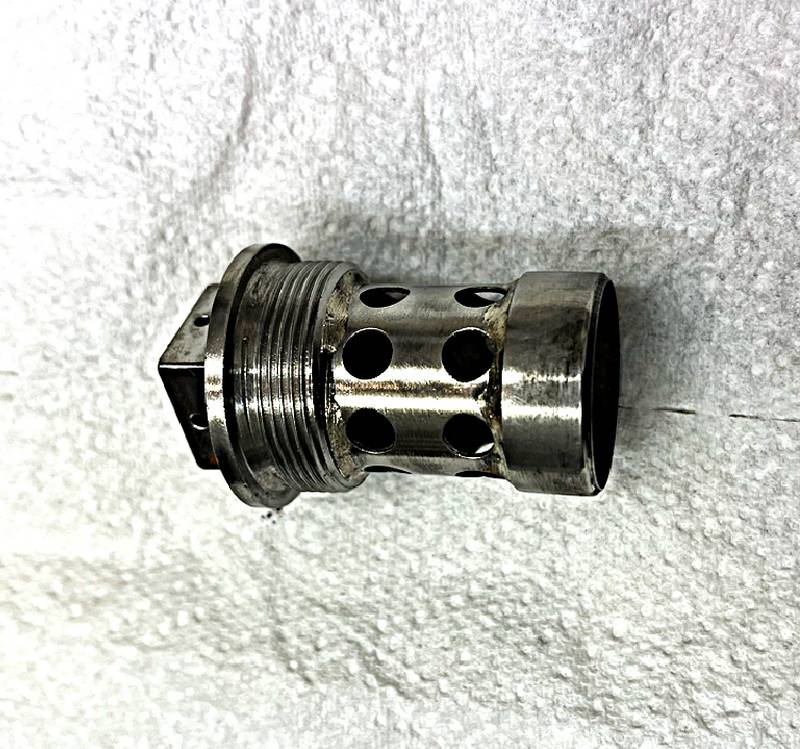
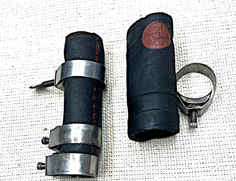
Wright Cyclone cylinder head moisture storage plugs, made by Chandler-Evans Corporate, South Meriden, Connecticut, United States of America. A Mary Ann Site find Burtonwood

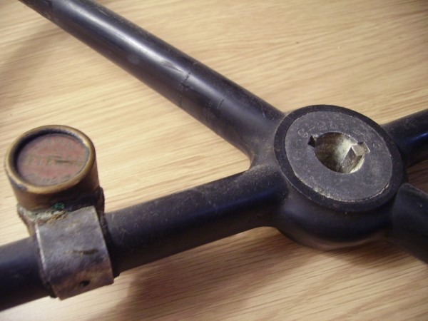
Recovered From George Howard's Scrap Yard Folly Lane (now closed) Which Was Well Known in the Area For Accepting Scrapped Aircraft Shortly After WWII. The item Was Recovered by Malc in 1987.
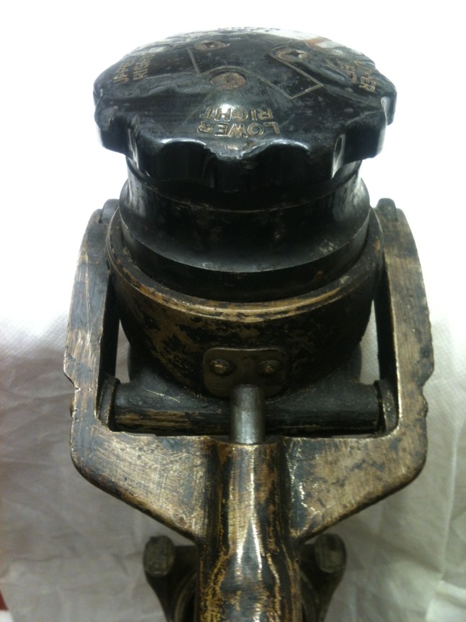
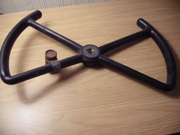
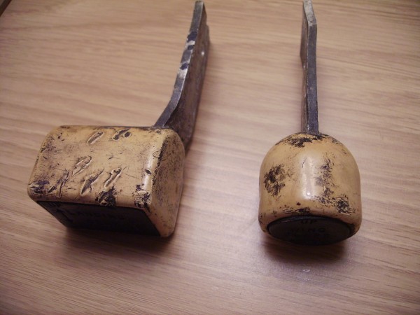
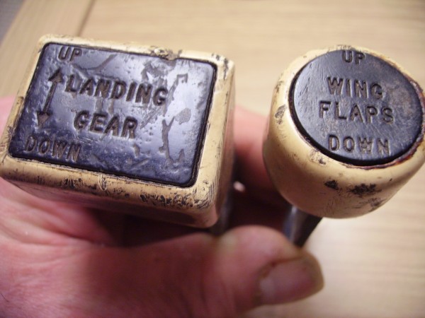
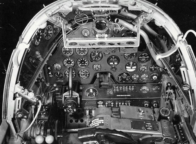
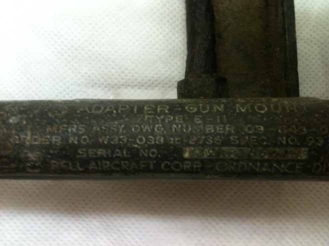
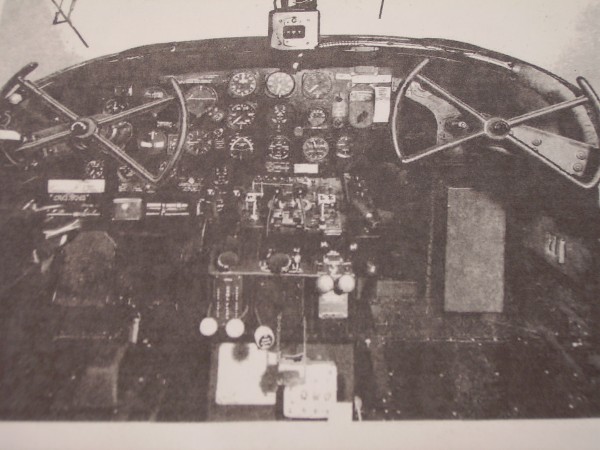
P-38 'H' Models Only. The handle can quite easily be seen below in this P-38 Cockpit photo.
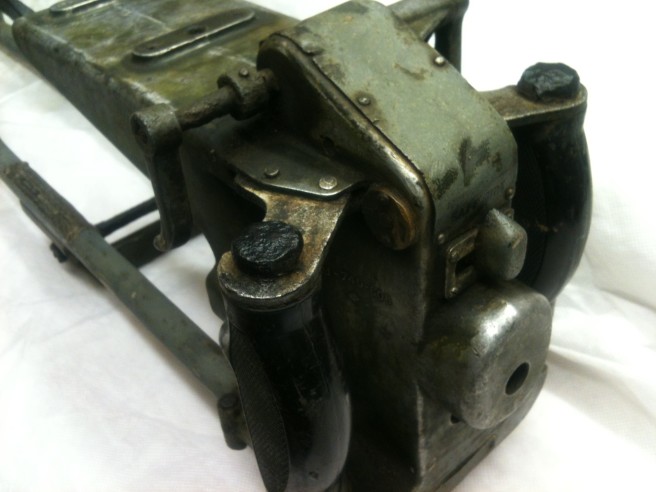
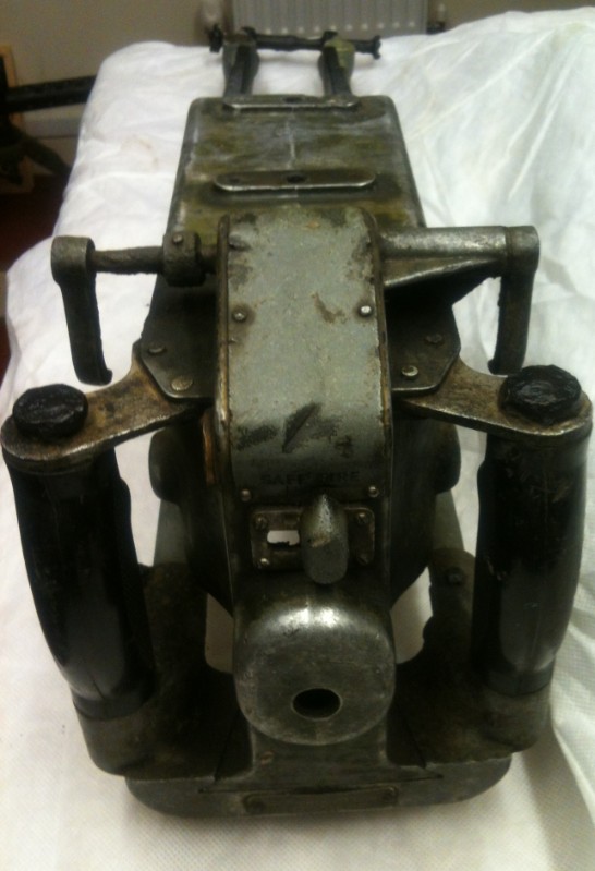
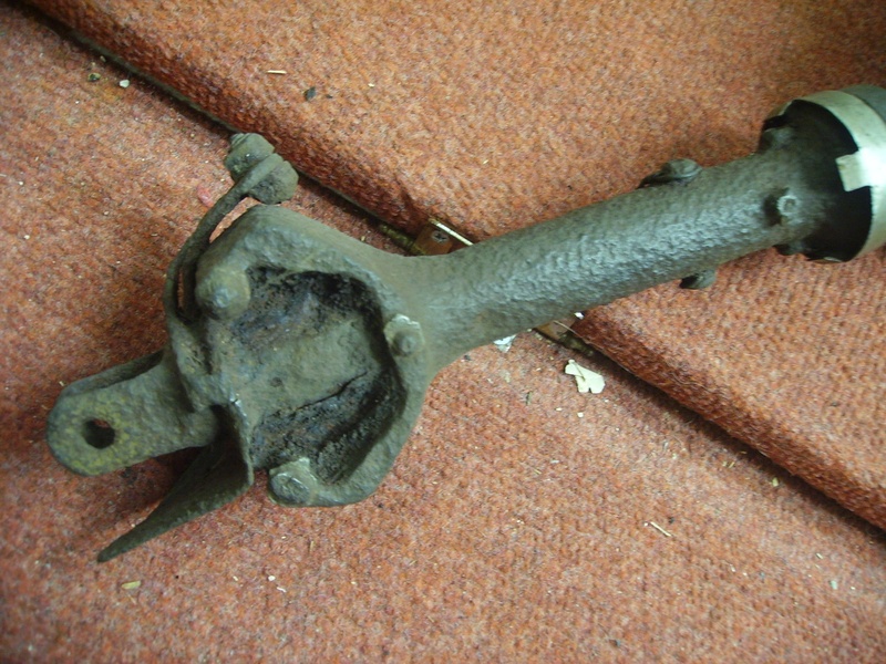
This Was Also Recovered From George Howard's Scrap Yard Folly Lane (now closed) This item Was Also Recovered by Malc in 1966.
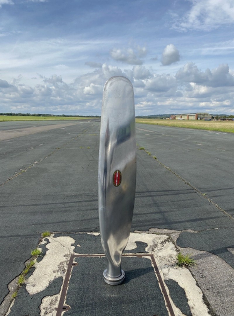
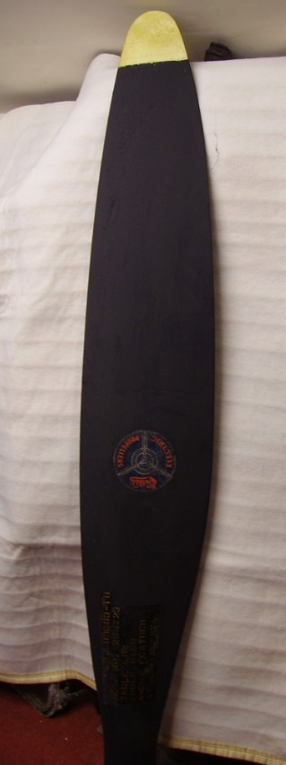
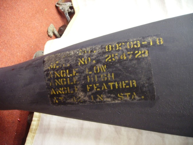
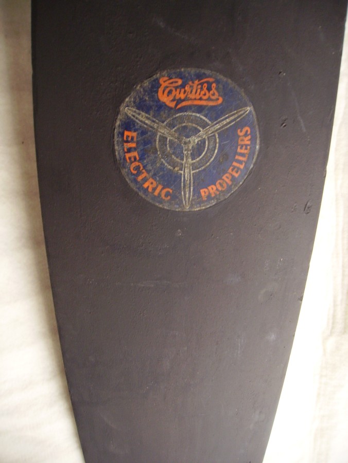
Electric Variable Pitch Propeller. Drawing No. 89303-18 (Left Side). This Prop Was Also Recovered From George Howard's Scrap Yard Folly Lane (now closed) This item Was Also Recovered by Malc in 1966.
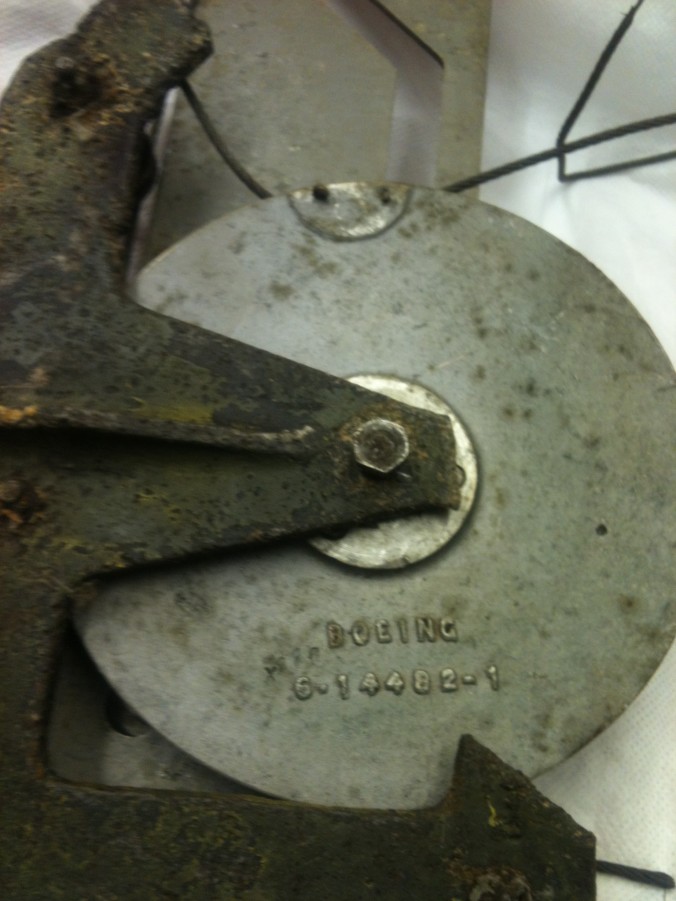
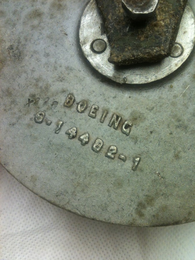
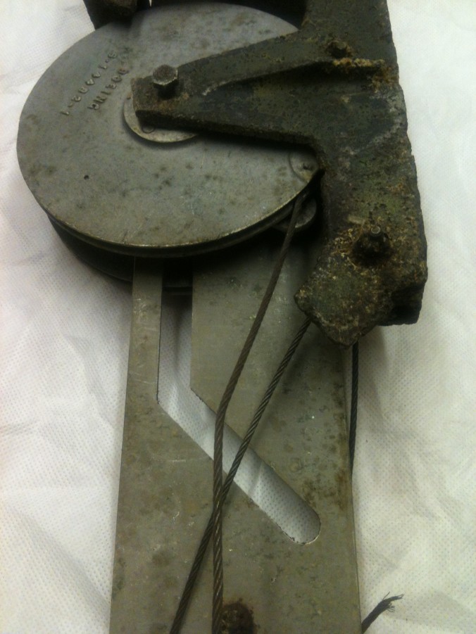
2 X Control Cable Pulley's Side by Side With Lugs on The Edge (on the inside of the wheel) To Allow For Forward and Backward Movement in the Grove on the Main Plate.
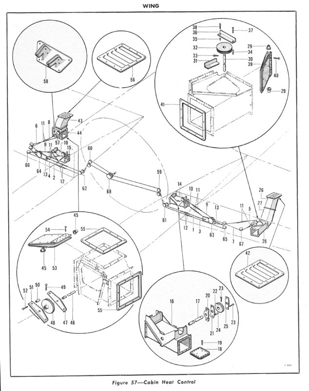
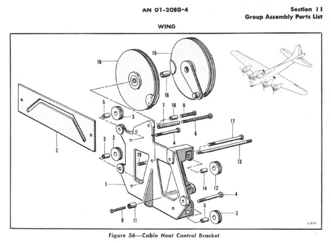
B-17G Cabin Heat Control Bracket Assembly, fitted inside the inner wings from the start of block B-17G-80-BO and equivalent Douglas and Vega built examples. (Thanks again to Paul Bellamy for his help finding out what this item was for and which aircraft it was fitted on as well)
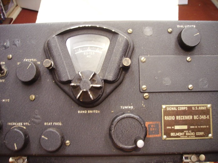
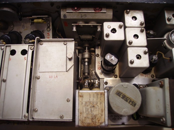
Communications Receiver. Made by Belmont Radio Corp, Chicago illinois - Serial number 547 Order Number 78WFSCPD-42 as used in all AAF Bombers & Transports. The receiver was powered with 28 volts primary wired to a DC Dynamotor giving an output of 235 volts at 75ma. There were 6 frequency bands. The frequency ranges are: Band 1 = 200 - 500 Hz Band 2 = 1.5 - 3.5 Mhz Band 3 = 3.5 - 6 Mhz Band 4 = 6 - 9.5 Mhz Band 5 = 9.5 - 13.5 Mhz Band 6 = 13.5 - 18 Mhz
Does Anyone Know What Aircraft This is From?
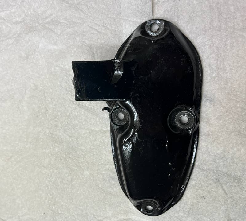
All I know about this is that it is from WW2 and is American . There is two small stamps on it one says 291 W and is in a circle , the other says 275 and that is also in a circle. Mike Davey (an 'Old' member from my previous website) says: "It's a flame damping exhaust. Looking at the mounting flange it doesn't look like it is off any kind of aero engine I know. It could be from an airfield vehicle?"
Driven Turbo Supercharger.
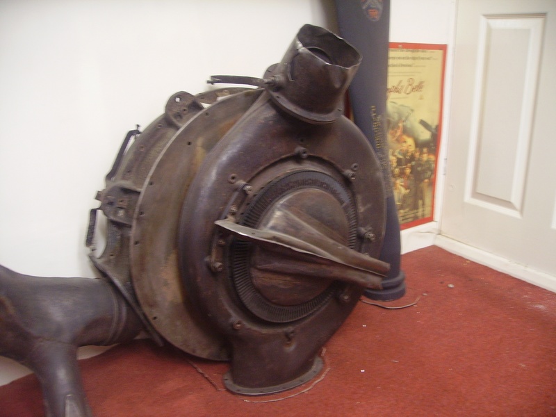
What is it from? This is from a Boeing B17 Flying Fortress. What does it do? It was essential in maintaining high altitude performance. The supercharger was driven by engine exhaust gases blowing a turbine bucket wheel to compress rarified air at high altitude and provide the engine carburetors with the necessary volume of air for efficient combustion. Where is this picture from? This one was taken in Malc's museum of military. (Malc is the owner of this website).
It's from a boeing B17 flying fortress.
It opens and closes the Bombay doors.
This picture was taken in Malc's Museum of Military.
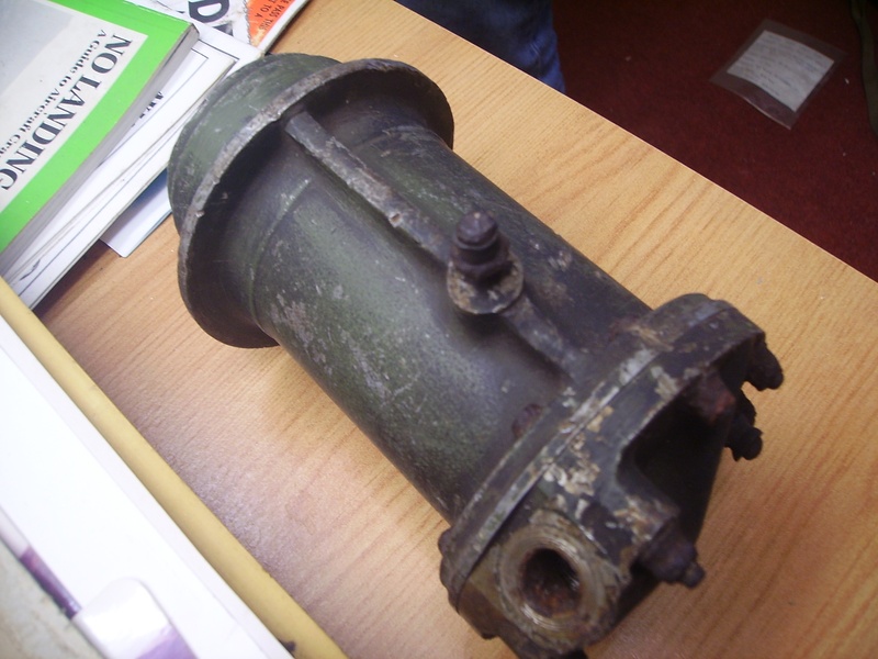
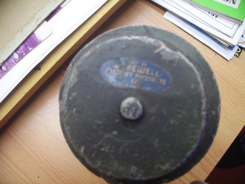
All we know is that it's manufactured by Bakewell Aircrafts Product company, Los Angeles. It has been painted a drab green colour and it only has one pipe outlet on it. There is also some numbers on it, we don't realy know what they mean either. Assembly number : 5073568-1 Other numbers : 4073961-1 , SET T 1571, C23, S56. There is also a circle that says : "GOT 12" on it. If anyone can tell us what this is then click on the 'Contact' button at the top of this page.
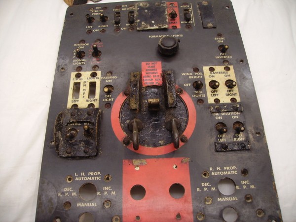
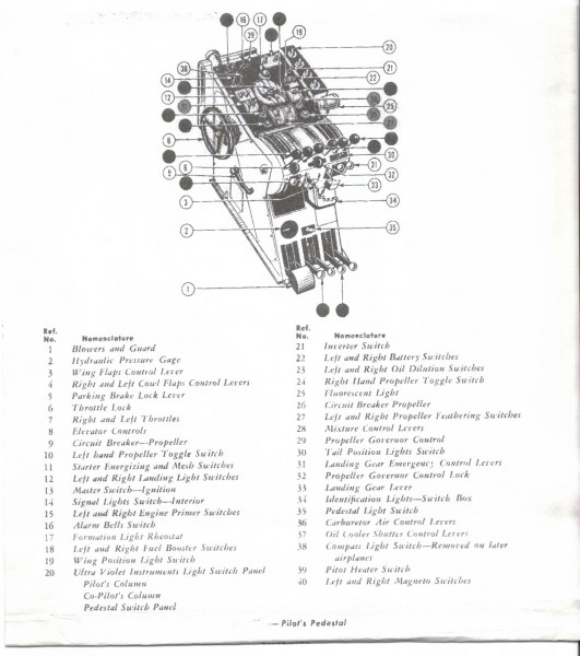
Pilot's Control Column.